
Arduino: LED and Digital GPIO
Build the embedded-systems Hello World and understand safe GPIO current.
◷ 30 minParts and tools
- Arduino Uno
- LED
- 220 Ω resistor
- Breadboard and jumper wires
Lesson
Learning objective
Build the embedded-systems Hello World and understand safe GPIO current.
Procedure
- Review the circuit and confirm the board voltage.
- Build and inspect the wiring before applying power.
- Upload the example, observe the result and record your readings.
- Change one parameter, predict the result and test again.
Troubleshooting
Check power, ground, pin selection, polarity, compiler target and serial output. Use a multimeter or logic analyser where appropriate.
Interactive circuit workspace
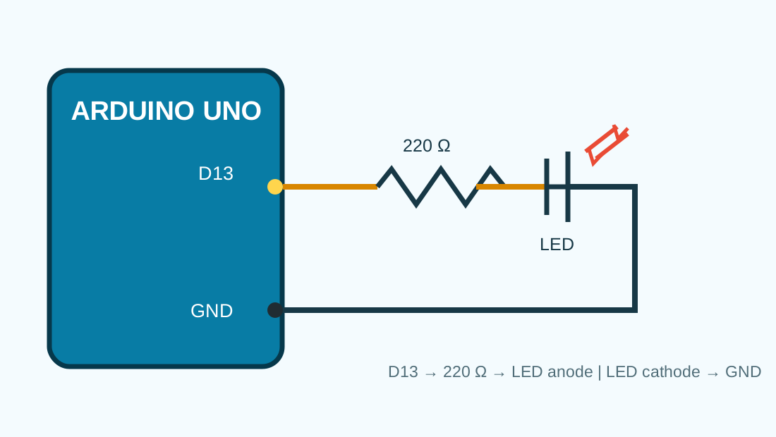
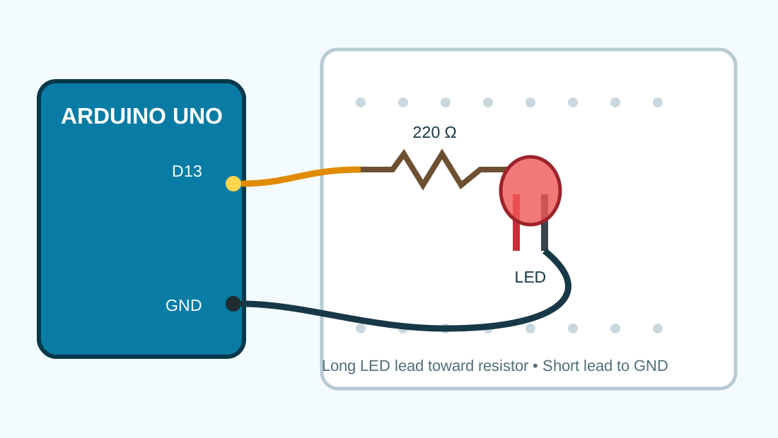
Pin-to-pin connections
| Board pin | Component pin | Purpose | Voltage |
|---|---|---|---|
| Arduino D13 | 220 Ω resistor input | LED control output | 5 V logic |
| Resistor output | LED anode (+) | Current limiting | Approx. 2 V LED drop |
| LED cathode (−) | Arduino GND | Return path | 0 V |
Electrical safety warnings
- Disconnect USB power before changing breadboard wiring.
- Never connect an LED directly without a current-limiting resistor.
- Observe LED polarity: the long lead is normally the anode (+).
- Do not exceed the board's permitted GPIO current.
- Ensure the development board and instrument share a common ground.
Measurement checkpoints
Multimeter
- With power disconnected, confirm there is no short between 5V and GND.
- Power the board and measure 5V relative to GND.
- Run the sketch and measure D13 in HIGH and LOW states.
- Measure directly across the LED while it is illuminated.
Expected readings
| Checkpoint | Expected | Tolerance | Instrument |
|---|---|---|---|
| 5V pin to GND | 5.0 V | 0.25 V | Multimeter DC voltage |
| D13 HIGH to GND | 5.0 V | 0.4 V | Multimeter DC voltage |
| Across red LED when ON | 1.8–2.2 V | 0.3 V | Multimeter DC voltage |
| D13 output | 1 Hz square wave | 10% | Oscilloscope |
Oscilloscope references
| Signal | Test point | Expected waveform / frequency |
|---|---|---|
| D13 output | D13 relative to GND | 0–5 V square wave, approximately 1 Hz |
Logic-analyser references
| Bus / signal | Settings | Expected result |
|---|---|---|
| Digital output | Channel 0 on D13, ground connected | Alternating HIGH/LOW every 500 ms |
Troubleshooting decision path
LED does not illuminate
Check: Confirm LED polarity and D13 selection
Action: Reverse the LED if incorrect and verify the sketch pin
LED stays continuously ON
Check: Check uploaded loop and accidental 5V connection
Action: Rewire the resistor input to D13
Upload fails
Check: Check board, USB data cable and COM port
Action: Select the correct board/port and retry
Board resets or becomes hot
Check: Disconnect power and test for a short
Action: Correct wiring before reconnecting USB
Bill of materials
Download BOM CSV| Qty | Component | Value / part | Notes |
|---|---|---|---|
| 1 | Arduino Uno compatible board | ATmega328P | 5 V board |
| 1 | LED | Red, 5 mm | Observe polarity |
| 1 | Resistor | 220 Ω, 0.25 W | Current limiting |
| 1 | Breadboard | Half size or larger | Solderless |
| 3 | Jumper wires | Male-to-male | Connections |
Lab observation report
Log in to record measurements, upload evidence and submit this practical for approval.
Log in to submitExample code
void setup(){ pinMode(LED_BUILTIN, OUTPUT); }
void loop(){ digitalWrite(LED_BUILTIN, HIGH); delay(500); digitalWrite(LED_BUILTIN, LOW); delay(500); }
Knowledge check
Why is a resistor used with an external LED?